Active Structure Element
The main active structure element for the Technology Layer is the node. This element is used to model structural entities in this layer which as the following characteristics:
- It is used to model application servers, database servers, or client workstations.
- It is often a combination of a hardware device and system software, thus providing a complete execution environment and It can consist of sub-nodes.
- It can be interconnected by communication paths.
- Artifacts can be assigned to (i.e., deployed on) nodes.
- Artifacts deployed on a node may either be drawn inside the node or connected to it with an assignment relationship.
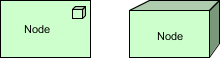
Node Concept Notation
A node is active processing element that is defined as a computational resource upon which artifacts may be stored or deployed for execution.
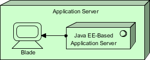
Node Concept Example
In the ArchiMate diagram below, you see an Application Server node, which consists of a Blade device and Java EE-based application server system software.
The name of a node should preferably be a noun.
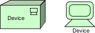
Device Concept Notation
A device is a specialization of a node that represents a physical resource with processing capability. It is typically used to model hardware systems such as mainframes, PCs, or routers.
A device is defined as a hardware resource upon which artifacts may be stored or deployed for execution and has the following characteristics:
- Devices are part of a node together with system software.
- Devices may be composite; i.e., consist of sub-devices.
- Devices can be interconnected by networks.
- Artifacts can be assigned to (i.e., deployed on) devices.
- System software can be assigned to a device.
- A device can consist of sub-devices.
- A node can contain one or more devices
- The name of a device should preferably be a noun referring to the type of hardware; e.g., “IBM mainframe”.
- Different icons may be used to distinguish between different types of devices; e.g. mainframes and PCs.
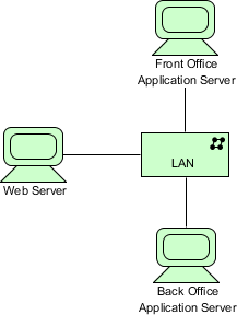
Device Concept Example
The ArchiMate Diagram below shows an example of a number of servers, modeled as devices, interconnected through a local area network (LAN).
System Software Concept Notation
System software represents a software environment for specific types of components and objects that are deployed on it in the form of artifacts, which
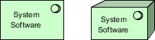
System software is a specialization of a node that is used to model the software environment in which artifacts run which has the following characteristics:
- System software can be used to represent, for example, an operating system, a JEE application server, a database system, a workflow engine, or COTS software i.e. ERP or CRM packages.
- System software may contain other system software; e.g., an operating system containing a database.
- System software is combined with a device representing the hardware environment to form a general node.
- System software can be assigned to a device.
- The name of system software should preferably be a noun referring to the type of execution environment; e.g., “JEE server”.
- Artifacts can be assigned to (i.e., deployed on) system software.
- A node can contain system software.
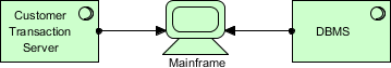
System Software Concept Example
In the ArchiMate Diagram below, we see a mainframe device that deploys two system software environments: a customer transaction server and a database management system (DBMS).
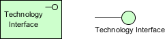
Technology Interface Concept Notation
A technology interface is defined as a point of access where technology services offered by a node can be accessed by other nodes and application components.
An technology interface specifies how the technology services of a node can be accessed by other nodes provided by the interface and it has the following characteristics:
- A technology interface exposes an technology service to the environment.
- A technology interface specifies a kind of contract that a component realizing this interface must fulfill.
- A technology interface may be part of a node through composition
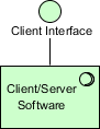
Technology Interface Concept Example
In the model below, we see a client technology interface exposed, which is part of the client/server system software.
The name of a technology interface should preferably be a noun.
Network Concept Notation
A network is defined as a communication medium between two or more devices.
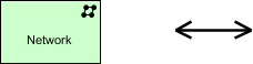
A network represents the physical communication infrastructure and it has the following characteristics:
- This may comprise one or more fixed or wireless network links.
- The most basic network is a single link between two devices.
- A network has properties such as bandwidth and latency.
- It embodies the physical realization of the logical communication paths between nodes.
- A network connects two or more devices.
- A network realizes one or more communication paths.
- A network can consist of sub-networks.
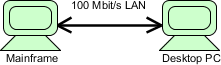
Network Concept Example
In the model below, a 100 Mb/s LAN network connects a mainframe and PC device.
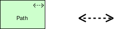
Communication Path Concept Notation
A communication path is defined as a link between two or more nodes, through which these nodes can exchange data.
- A communication path is used to model the logical communication relations between nodes which has the following characteristics:
- It is realized by one or more networks, which represent the physical communication links.
- The communication properties (e.g., bandwidth, latency) of a communication path are usually aggregated from these underlying networks.
- A communication path connects two or more nodes.
- A communication path is realized by one or more networks. A communication path is atomic.
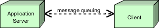
Communication Path Concept Example
In the ArchiMate Diagram below, we see a communication path “message queuing” between an Application Server and a Client.