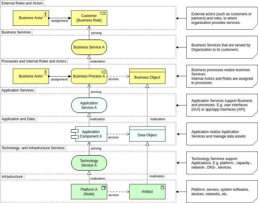
A central tenet of Enterprise Architecture is achieving business-IT alignment: ensuring that the Business, Application, and Technology Layers are coherently matched and support the organization’s purpose. ArchiMate provides specific relationships, primarily Serving and Realization, to model the links and dependencies that span these three core layers.
Elements that link these different aspects and layers play a central role in providing a coherent architectural description. This guide details how ArchiMate uses these relationships to model structural support, behavioral provision, and the materialization of abstract concepts across the architecture.
I. Serving Relationships: Modeling Behavioral and Structural Support
The Serving relationship is the most important relationship between layers and forms a key Dependency Relationship in ArchiMate. It represents a control dependency, denoting that a source element provides its functionality to a target element.
Serving relationships describe how services or interfaces offered by an element are utilized by entities in their environment, often linking a service from a lower layer to a process or actor in a higher layer.
Cross-Layer Serving Examples:
Serving relationships establish the vertical support structure of the enterprise, often moving upwards from Technology to Business:
| Supporting Layer | Served Layer | Relationship Direction | Example | Citation |
|---|---|---|---|---|
| Application Layer | Business Layer | Application Service serves Business Behavior elements (Process, Function). | An Application Service serves a Pay Invoices Business Process. | |
| Application Layer | Business Layer | Application Interface serves Business Roles. | The Payment Interface serves the Customer (Business Actor/Role). | |
| Technology Layer | Application Layer | Technology Service serves Application Behavior elements (Process, Function). | A Messaging Technology Service serves an Obtain Travel Insurance Application Process (hypothetical). | |
| Technology Layer | Application Layer | Technology Interface serves Application Components. | A Web Server Port Technology Interface serves a Quotation Application Component (hypothetical). |
II. Realization Relationships: Modeling Abstraction and Materialization
The Realization relationship is a Structural Relationship that indicates that an element plays a critical role in the creation, achievement, sustenance, or operation of a more abstract element. It is used to show how tangible elements (the “how” or physical) realize more abstract elements (the “what” or logical).
A. Realization of Behavior (Processes and Functions)
Realization is used to model how the high-level business functions and processes are implemented or supported by software behavior:
- Application Realizing Business Behavior: An Application Process or Application Function realizes a Business Process or Business Function.
- Example: A Transaction Processing Business Function is realized by a Billing Service Application Service.
- Technology Realizing Application Behavior: A Technology Process or Technology Function can realize an Application Process or Application Function.
B. Realization of Structure (Information and Data)
Realization is essential for showing how abstract business concepts materialize into structured data and physical files across the layers:
| Abstract Element | Realizing Element | Description | Citation |
|---|---|---|---|
| Business Object (Conceptual Information) | Data Object (Application Data) | A Data Object is a digital representation of the corresponding Business Object. | |
| Data Object (Application Data) | Artifact (Physical File/Data) | The Artifact (e.g., a physical data file or table) realizes the Data Object. | |
| Business Object (Conceptual Information) | Technology Passive Structure Element (Physical Representation) | A technology passive structure element (like an Artifact) may realize a Business Object, indicating it is the physical representation of that business object. |
Example of Passive Structure Materialization: A high-level Business Object like “Insurance Policy” is realized by a Data Object in the Application Layer (e.g., “Policy Record”). This Data Object, in turn, is realized by an Artifact (e.g., “policy_db.sql” or a physical data file) in the Technology Layer. Due to derivation, the Artifact indirectly realizes the original Business Object.
C. Realization of Components (Logical to Physical)
The realization relationship also links logical components to their physical implementations:
- Artifact Realizing Application Component: An Artifact (which represents a “physical” component that is deployed on a Device or System Software) can realize an Application Component. This shows that a deployed executable file (Artifact) constitutes the logical software component.
III. Key Considerations for Cross-Layer Alignment
When aligning the core layers, certain rules must be observed:
- Alignment of Business Actors: Business Internal Active Structure elements (e.g., Business Actors or Business Roles) cannot be realized by Application or Technology elements, because people cannot be realized by technology. Instead, the behavior (Business Processes or Business Functions) assigned to those active structures is realized by the Application or Technology behavior elements.
- Aggregation of Products: A Product (a composite element in the Business Layer) may have an Aggregation relationship with an Application Service, Technology Service, or Passive Structure element from lower layers to indicate that these items are offered directly to a customer as part of the product.
- Derived Relationships: Since ArchiMate allows the derivation of relationships through chains (e.g., Realization leading to Realization), it is possible to draw relationships directly between the Business and Technology Layers, abstracting away the intermediate Application Layer elements.
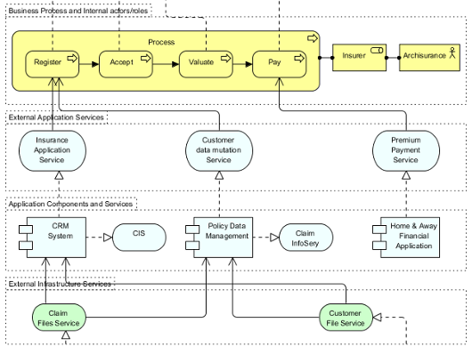
Comprehensive Cross-Layer Example Overview
To integrate these concepts, a single view often uses the Serving relationship to connect behavior across layers and the Realization relationship to connect information structures:
In a cross-layer view (like Example 31 in the sources, often using colors or layer letters to distinguish elements), the following links would integrate the layers:
- Business Goal to Business Process: A high-level Business Goal (e.g., “Reduce Claim Time”) might influence or be realized by changes to a Business Process (e.g., “Adjudicate Claim”).
- Business to Application (Serving): The “Adjudicate Claim” Business Process is served by an Application Service (e.g., “Claim Status Update”).
- Application to Business (Realization): The Claim Status Update Application Service is internally realized by an Application Function (e.g., “Update Claim Records”).
- Application to Technology (Serving): The Application Component (e.g., “Claim System”) that performs this function is, in turn, served by a Technology Service (e.g., “Database Access Service”).
- Information Flow (Realization Chain): A Business Object (e.g., “Claim”) is realized by a Data Object (e.g., “Claim XML File”) which is itself realized by an Artifact (the physical XML file stored on a server).
- Deployment: The Artifact (the Claim XML File) is assigned to or located on a Device or System Software (Node) in the Technology Layer.
This chain of relationships provides the structure necessary to understand the dependencies and impacts of changes across the entire enterprise architecture.
Visual Paradigm Tools and Resources for ArchiMate Modeling
Visual Paradigm is a leading, Open Group-certified tool for ArchiMate (supporting up to version 3.2 as of December 2025). It offers robust features like full notation support, viewpoint management, TOGAF integration, and innovative AI-powered diagram generation for rapid prototyping.
Key Tools in Visual Paradigm for ArchiMate
- Desktop Edition (Enterprise recommended): Full-featured for professional modeling, including AI Diagram Generator for ArchiMate, custom viewpoints, resource catalogs, and real-time collaboration.
- Visual Paradigm Online (Free Edition available): Web-based tool for quick ArchiMate diagrams – ideal for beginners or lightweight use. Supports drag-and-drop and templates.
- AI Diagram Generator & Chatbot: Generate compliant ArchiMate diagrams and all official viewpoints instantly from text prompts (e.g., “Model a coffee shop’s business layer with SaaS support”). Refine iteratively via natural language.
- TOGAF ADM Guide-Through: Integrates ArchiMate modeling directly into TOGAF phases for structured enterprise architecture development.
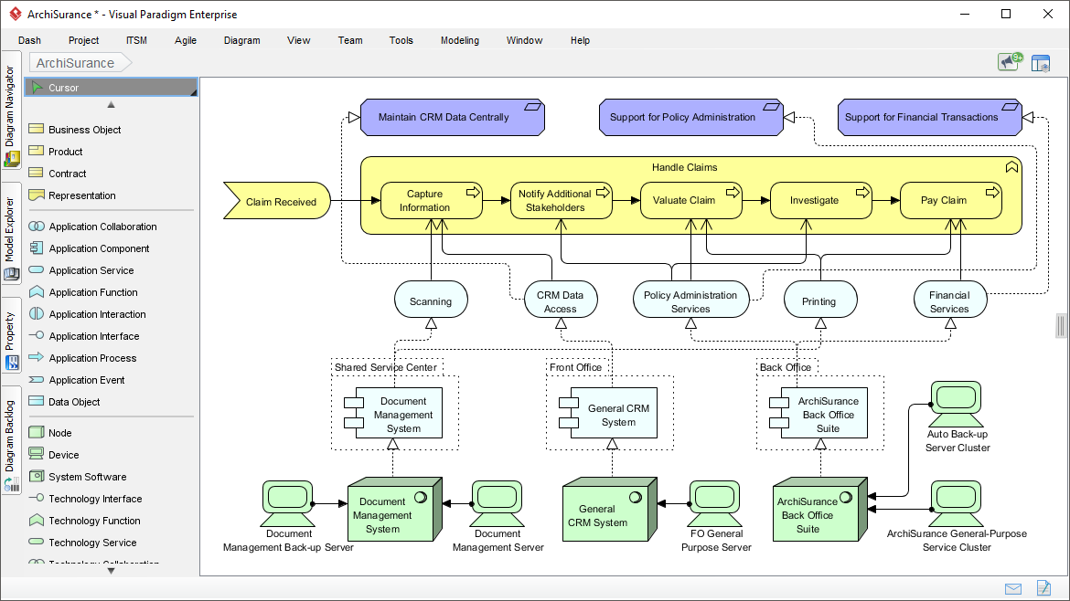
Here are some example screenshots of ArchiMate diagrams and the interface in Visual Paradigm:


Recommended Articles and Tutorials
These official Visual Paradigm resources provide step-by-step guidance, examples, and best practices:
- Comprehensive Tutorial on ArchiMate – In-depth overview of layers, elements, relationships, and useful diagram types with examples. Link: https://guides.visual-paradigm.com/comprehensive-tutorial-on-archimate/
- Full ArchiMate Viewpoints Guide (with Examples) – Detailed handbook covering all 23 official viewpoints, complete with diagram examples drawn in Visual Paradigm. Link: https://www.visual-paradigm.com/guide/archimate/full-archimate-viewpoints-guide/
- ArchiMate Diagram Tutorial – Step-by-step guide on creating diagrams, including online tool access. Link: https://online.visual-paradigm.com/diagrams/tutorials/archimate-tutorial/
- How to Draw ArchiMate Diagrams – Practical tutorial with notations and sample creation. Link: https://www.visual-paradigm.com/tutorials/how-to-draw-archimate-diagram.jsp
- Generate ArchiMate Diagrams and Viewpoints Instantly with AI – Explains the new AI feature for fast generation (updated December 2025). Link: https://updates.visual-paradigm.com/releases/ai-archimate-viewpoints-generator/
- Using ArchiMate with TOGAF ADM – Integration guide for structured EA processes. Link: https://www.visual-paradigm.com/guide/archimate/using-archimate-tool-with-togaf-adm/
Start with the free online tool or trial the desktop version to experiment with the “Coffee Around The Corner” case study – the AI generator can create a baseline model from a simple prompt!