Introduction
The Physical Layer in ArchiMate is a powerful tool for modeling the tangible aspects of an enterprise architecture, particularly in environments where physical assets and operational technology (OT) are crucial. This tutorial explores the practical applications of the Physical Layer, providing detailed explanations and numerous examples to illustrate its versatility and importance in various industries.
Physical Layer Example
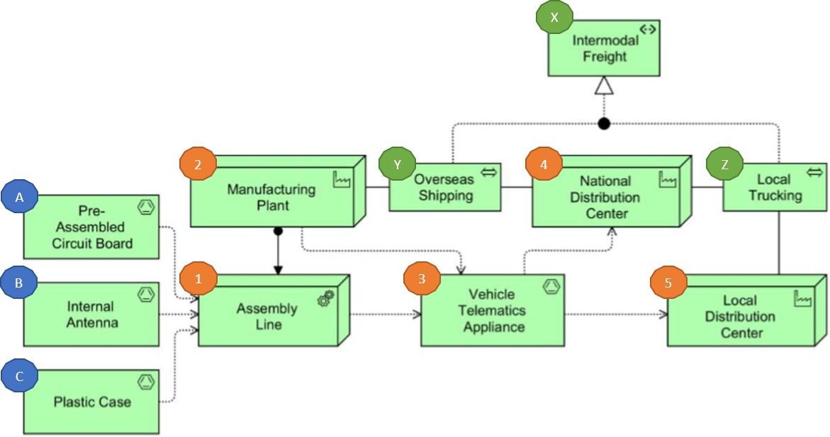
An (1) Assembly Line, modeled as equipment, and installed at a facility (2) Manufacturing Plant, makes use of materials (A) Pre-Assembled Circuit Board, (B) Internal Antenna, and (C) Plastic Case to produce material (3) Vehicle Telematics Appliance.
The appliance, initially located at the (2) Manufacturing Plant facility, is subsequently transported to the facilities (4) National Distribution Center and Local Distribution Center, making use of the distribution networks (X) Overseas Shipping and (Y) Local Trucking. These distribution networks together realize the path (Z) Intermodal Freight.
1. Manufacturing and Production Processes
The Physical Layer can model manufacturing scenarios by representing equipment, facilities, and materials involved in production. This application is essential for visualizing and optimizing production processes.
Example: Candy Factory
- Material Flow: The Physical Layer can depict the flow of materials, such as chocolate and wrappers, through various machines like melters, mixers, and wrapping machines. This visualization helps in understanding the entire production process from raw materials to finished products.
- Equipment Representation: Each machine in the production line can be modeled as a physical component, showing its role and interactions with other machines. For instance, the melter can be linked to the mixer, which in turn is connected to the wrapping machine.
- Facility Layout: The physical layout of the factory, including the arrangement of machines and storage areas, can be modeled to optimize space utilization and workflow efficiency.
Example: Automotive Assembly Line
- Material Flow: The flow of components like engine parts, chassis, and tires through the assembly line can be modeled.
- Equipment Representation: Robotic arms, welding machines, and paint booths can be represented as physical components.
- Facility Layout: The arrangement of assembly stations, quality control points, and storage areas can be visualized to improve production efficiency.
2. Logistics and Supply Chain Management
The Physical Layer enables the modeling of logistics networks that facilitate the movement of goods, helping organizations optimize supply chain operations and improve efficiency.
Example: Global Supply Chain
- Distribution Networks: The Physical Layer can model distribution networks, including shipping routes, transport methods (e.g., trucks, ships), and delivery schedules.
- Warehouse Management: Physical components like warehouses, loading docks, and sorting machines can be represented to optimize storage and handling processes.
- Transportation Flow: The flow of goods from manufacturing plants to distribution centers and retail locations can be visualized to identify bottlenecks and improve efficiency.
Example: E-commerce Logistics
- Distribution Networks: The network of fulfillment centers, delivery routes, and last-mile delivery options can be modeled.
- Warehouse Management: Automated storage and retrieval systems, conveyor belts, and packing stations can be represented.
- Transportation Flow: The flow of products from suppliers to fulfillment centers and then to customers can be visualized to optimize delivery times and reduce costs.
3. Integration of IT and OT
The Physical Layer allows for the seamless integration of information technology (IT) and operational technology (OT), which is vital for implementing IoT solutions and smart manufacturing environments.
Example: Smart Manufacturing
- Sensor Integration: Sensors on manufacturing machines can be modeled to show how they collect data and interact with control systems.
- Control Systems: The control systems that manage the operations of machinery can be represented, illustrating how IT systems govern physical processes.
- Data Flow: The flow of data from sensors to IT systems for processing and analysis can be visualized to support better decision-making.
Example: Smart Grid
- Sensor Integration: Sensors on energy generation equipment (e.g., solar panels, wind turbines) can be modeled to show how they monitor energy production.
- Control Systems: The control systems that manage energy distribution can be represented, illustrating how IT systems optimize energy flows.
- Data Flow: The flow of data from sensors to IT systems for energy consumption analysis and optimization can be visualized.
4. Facility Management
Organizations can use the Physical Layer to manage facilities by modeling physical spaces, maintenance schedules, resource allocation, and spatial relationships.
Example: Office Building
- Physical Spaces: The layout of offices, conference rooms, and common areas can be modeled to optimize space utilization.
- Maintenance Schedules: The maintenance schedules for HVAC systems, elevators, and other facilities can be represented to ensure timely upkeep.
- Resource Allocation: The allocation of resources like desks, meeting rooms, and equipment can be visualized to support effective facility management.
Example: Production Plant
- Physical Spaces: The layout of production lines, storage areas, and quality control stations can be modeled to optimize workflow.
- Maintenance Schedules: The maintenance schedules for machinery, conveyor belts, and other equipment can be represented to minimize downtime.
- Resource Allocation: The allocation of resources like raw materials, tools, and safety equipment can be visualized to support efficient production.
5. Energy Management
In sectors like smart grids or renewable energy, the Physical Layer can model components such as energy generation equipment, storage systems, and distribution networks.
Example: Renewable Energy Plant
- Energy Generation Equipment: Solar panels, wind turbines, and other renewable energy sources can be modeled to show their capacity and output.
- Storage Systems: Battery storage systems can be represented to illustrate how energy is stored and released.
- Distribution Networks: The network of power lines, substations, and transformers can be modeled to optimize energy distribution.
Example: Smart Grid
- Energy Generation Equipment: Distributed energy resources like rooftop solar panels and community wind farms can be modeled.
- Storage Systems: Large-scale battery storage systems can be represented to support grid stability.
- Distribution Networks: The network of smart meters, sensors, and communication systems can be modeled to optimize energy consumption and reduce losses.
6. Infrastructure Planning
The Physical Layer assists in planning infrastructure projects by modeling physical assets such as roads, bridges, and utilities, and their interactions with technology components.
Example: Urban Infrastructure
- Physical Assets: Roads, bridges, tunnels, and public transportation systems can be modeled to visualize the infrastructure layout.
- Technology Integration: The integration of smart traffic management systems, surveillance cameras, and communication networks can be represented to support urban planning.
- Impact Analysis: The implications of infrastructure changes on overall enterprise architecture can be analyzed to support decision-making.
Example: Smart City
- Physical Assets: Buildings, parks, and public spaces can be modeled to optimize urban design.
- Technology Integration: The integration of smart lighting systems, waste management systems, and environmental sensors can be represented to support sustainability goals.
- Impact Analysis: The impact of new infrastructure projects on traffic flow, energy consumption, and public safety can be analyzed to support urban development.
Conclusion
The Physical Layer in ArchiMate provides a versatile framework for modeling various aspects of enterprise architecture that involve physical components. Its applications span manufacturing, logistics, facility management, energy management, and infrastructure planning, demonstrating its importance in bridging the gap between operational technology and information systems. By leveraging the Physical Layer, enterprise architects can create comprehensive models that illustrate the interplay between physical and technological components, leading to better decision-making and operational efficiency.
By understanding and applying the practical applications of the Physical Layer, organizations can optimize their operations, improve efficiency, and achieve better alignment between their physical assets and technological infrastructure. This comprehensive approach ensures that both physical and technological resources are optimally utilized, contributing to the overall success of the enterprise.
ArchiMate References
Here is a reference list on ArchiMate by adopting Visual Paradigm for EA teams:
-
Best ArchiMate Software: This article discusses how Visual Paradigm’s ArchiMate tools facilitate communication of architectural designs among stakeholders and EA team members. It highlights the ability to model business processes with BPMN, design IT solutions with UML, and create various diagrams linked to ArchiMate for better traceability. The tool is certified by The Open Group and supports the full vocabulary and syntax of ArchiMate 3.1, making enterprise architecture design more straightforward1.
-
What is ArchiMate?: This guide provides an overview of ArchiMate, explaining its framework that divides enterprise architecture into business, application, and technology layers. It discusses the active support from the ArchiMate Forum of The Open Group and how ArchiMate’s well-founded concepts provide precision in modeling. The article also mentions the integration of ArchiMate with existing methods like TOGAF and its support by numerous consultancies and software tools2.
-
Visual Paradigm TOGAF ADM Tool: This article emphasizes how Visual Paradigm’s TOGAF ADM Tool empowers EA teams with innovative features, streamlined processes, and enhanced collaboration. It discusses the importance of consistency across EA projects and the ease of reusing existing elements in new designs. The article also highlights the customizable viewpoints and configurable architecture repositories that make Visual Paradigm a valuable tool for EA teams3.
-
Composition Relationship in ArchiMate EA Modeling: This article explains the composition relationships in ArchiMate and how Visual Paradigm supports EA projects with a comprehensive set of modeling tools. It discusses the features for requirement management, project management, and documentation, as well as the collaboration and teamwork facilitated by Visual Paradigm’s cloud-based services. The article also mentions the version control and change tracking features that enhance collaboration in EA teams5.
-
Step-by-Step Enterprise Architecture Tutorial with TOGAF: This tutorial provides a step-by-step guide to applying TOGAF in enterprise architecture development using Visual Paradigm. It explains how to create ArchiMate diagrams and produce TOGAF deliverables with ease. The tutorial also discusses the tools and diagrams provided by Visual Paradigm for analysis and documentation, including ArchiMate 3 diagrams and various viewpoints6.
-
Mastering ArchiMate: A Comprehensive Guide to Enterprise Architecture Modeling: This guide offers an in-depth look at ArchiMate and its use in enterprise architecture modeling. It discusses the flexibility of ArchiMate in creating various viewpoints relevant to different stakeholders and the importance of using a standardized language and notation for clear communication. The guide also highlights the use of colors in ArchiMate models to enhance understanding and interpretation7.
-
Guide-Through Process for EA and ITSM: This article discusses how Visual Paradigm’s Guide-Through Process helps in enterprise architecture and project management initiatives. It explains the steps involved in performing activities required in EA development and IT project management, including visual modeling with ArchiMate diagrams. The article also mentions the integration of EA processes with Agile software development using Visual Paradigm’s built-in task manager8.
-
Understanding the Purpose of ArchiMate: A Guide for Enterprise Architects: This guide provides an overview of ArchiMate and its purpose in enterprise architecture. It discusses the features of Visual Paradigm’s ArchiMate Diagram Editor, including its intuitive interface and collaboration tools. The guide also explains how ArchiMate viewpoints provide predefined perspectives for creating architectural models and simplifying complex information for different stakeholders9.
-
ArchiMate Viewpoint Archives: This article discusses the use of ArchiMate viewpoints in providing predefined perspectives for creating architectural models. It explains how viewpoints help focus on specific aspects or concerns of the architecture, making it easier to communicate complex information to different stakeholders. The article also mentions the use of ArchiMate in aligning IT strategies with business goals and ensuring compliance with standards like ISO 2700110.
These references provide a comprehensive overview of how Visual Paradigm’s ArchiMate tools and features support EA teams in modeling, collaborating, and communicating complex enterprise architectures.